Nothing beats an old-school tactile-clicky keyboard for typing feel, durability, and classic engineering style. A surface feature of this kind of keyboard that contributes to the typing feel and durability is a heavy and rigid case.
The center of any discussion of classic heavy keyboards is always the line of development that ran from IBM beam-spring keyboards in the 1970s down through the buckling-spring Model F and Model M in the 1980s and 1990s to today’s Unicomps and the New Model F.
This document is a guide to recognizing, restoring, maintaining, and modifying classic heavy keyboards. "Restoring" is prominent because the type has not been manufactured in volume since cost pressure drove them out of the market in the mid-1990s in favor of flimsier and cheaper products.
This document was formerly the "Model M Troubleshooting FAQ", until it got mission creep.
Background
Model M
Production of Model Ms began in 1985 and continues to the present day, though spread across four different manufacturers and with major fluctuations in volume and quality. The details are complex and best summarized at its Wikipedia article, which the author of this FAQ helped fill out.
Troubleshooting and restoration of vintage Model Ms remains attractive because, while the buckling-spring keyswitch is unchanged dince its beginnings, relentless cost pressure led to a steady decrease in build quality of the cases and structral backplates. This decline was partly reversed by Unicomp’s tooling refresh in 2020, but the old-style IBM heavy case that is so valued by enthusiasts has not been returned to production.
Model F
The very first buckling-spring keyboard, the Model M’s predecessor, was the Model F, produced mainly from 1981 to 1985 and at much lower volume until 1994. This was the keyboard attached to the original IBM Personal Computer, the PC XT, and early versions of the PC AT. It is nowadays referred to as the "XT keyboard", though it predated the XT. The PC version had 83 keys (88 distinct switches); some industrial versions had 122 keys.
Many buckling-springs enthusiasts consider the Model F variant of the buckling-spring switch to be superior to the Model M’s; the actuation force is lower and the tactility a bit crisper. Despite this, vintage model Fs are in much less use today than Ms. Fewer were produced, fewer have survived, and the pre-ANSI layout is offputting to a lot of potential users.
Model F Labs will sell you a hand-crafted recreation of the Model F with a somewhat more modern ANSIfied layout. While it is eye-wateringly expensive, it speaks USB natively and almost no interoperability issues have been reported with modern hardware. (I’ve heard of one sporadic failure to initialize connecting to Windows.)
Beam-spring keyboards
Before the Model F, the beam spring. Very few of these survive, and this FAQ cannot yet say much about troubleshooting and restoring them beyond reporting on some known issues and failure modes. Watch this space.
Model F Labs has announced a revival of the beam spring for after their New Model F production run finishes.
Identification
Model M
The Wikipedia article on the Model M has a "Features by part number" chart that may help you identify the precise variant you are troubleshooting. The model number can usually be found on a sticker applied to the lower surface of the case.
The following table may help in identifying the manufacturing generation of a Model M keyboard, and expresses the reduction in unit weight over time. It is originally from Thomas Ran (chyrosran22). Each model number is representative, but there are typically many other models per generation. The sample size for each was 1; weights may vary slightly from those listed.
| Model | Badge | Year | Generation | Total wt | Case wt | Plate thickness |
|---|---|---|---|---|---|---|
1388302 |
square black |
1985 |
0 |
2.38kg |
900g |
1.3mm, rainbow |
1390136 |
square silver |
1987 |
1 |
2.24kg |
800g |
1.2mm, rainbow |
1351406 |
black oval |
1987 |
1 |
2.25kg |
806g |
1.2mm, rainbow |
1391401 |
black oval |
1991 |
2 |
2.06kg |
820g |
1.0mm, gray |
1391406 |
blue oval |
1996 |
3 |
2.01kg |
799g |
1.0mm, gray |
1370477 |
blue oval |
1995 |
3 |
2.00kg |
943g |
0.8mm, gray |
UB343H4 |
unicomp |
2009 |
4 |
1.67kg |
626g |
0.8mm, gray |
The most common single type is the 1391401, which shipped with the IBM PS/2 beginning in 1987.
More details on generations 1-4 can be found under "Generations" here. Note that the earliest Generation 4 variants were shipped by Lexmark and are not represented in the table above.
There were many iterations of the Model M controller board. They can be told apart by the number of ribbon cables running from the keyboard membrane. Membranes and controllers from different generations are not compatible.
The initial design had three ribbon connectors with 16 column, 8 row, and 4 LED pins. These were used on all 101- and 102-key Model Ms before 1991, and continued to ship on some keyboards into the early 1990s. These controllers exposed an SDL jack on the back of the case, and had through holes that mate to plastic pegs to either side of the opening for the jack.
Around 1993 Lexmark switched to fixed cables and occluded the jack opening with a plastic shim that locked to a strain reliever on the cable, which was internally wired to a cheaper Molex connector.
At some point in the early 1990s the 16-8-4 arrangement of the connectors changed to two connectors with 16 row pins and 12 column plus LED pins.
The final variant, first shipped in 1995 and still being made today by Unicomp, had no ribbon cables at all. In these, a small PCB with integrated LEDs sat just below the lock light panel with connectors on it touching the membrane, replacing the larger PCB that formerly sat behind the backplate or was bolted to it.
Aficionados refer to the small PCB as the "press-fit controller". It has a known problem that the plastic pegs holding down the contact surface on the PCB tend to degrade and snap off in 5-7 years. This makes the keyboard unsalvageable and good only as a parts donor.
M122s use a controller with 20- and 8-pin membrane connectors. Controller boards for these are not interchangeable with any of the previous varieties.
Up until Unicomp, the physical dimensions of the M were normally 19.3" (48.9 cm) x 8.2" (20.8 cm) x 1.9" (4.9 cm). Some variants such as 122s and Space Savers differed. Unicomp Ms have smaller, lighter cases. The New Model M is 17.9" = 45.5cm x 7.5" = 19.0cm x 196" = 5.0cm).
Until some time in the Unicomp period (after 2001) cases and keys were both PBT. Unicomp retained PBT keys but the cases became an ABS/polycarbonate blend.
Model F
Model F keyboards also usually have a provenance sticker giving the part number. For identification tips on Model F types, see the Wikipedia entry
Beam spring
Surviving examples of beam-spring keyboards are extremely rare, enough so that I have not been able to gather systematic information on identifying them. A Google Images search for "beam-spring keyboard" does yield images of several relatively common types. Many of the survivors were built for either the Displaywriter or the 3278 and 5250-series terminals.
Testing
If you are running Linux and have doubts about whether any keys are operating, xev(1) will display keypress/key-release events and what keystroke X interprets them as. Here’s the command:
$ xev -event_mask keyboardVisually easier testers that are less stringent (don’t give you separate confirmation of a key release) abound on the web and can be found with a search for "keyboard tester". This one is well adapted to testing ModeL Ms.
Disassembly and reassembly
Before disassembling any of these keyboards it’s a good idea to search the web for restoration videos to see how it’s done. Links to some of the better ones can be found in the [references] near the end of this FAQ.
Take pictures before disassembling, especially if the keyboard has a layout anything other than bog-standard ANSI. You want to be able to put the keycaps back on correctly…
One thing to be careful of during reassembly of either an M or an F, before you start re-inserting keys: check carefully that no spring is caught over the edge of its barrel. If you try reinserting a key with the spring caught like that, you will crush and deform the spring, ruining it. Then you’ll have to take the board back apart and replace the flapper, which is a huge pain.
Model M
Once the case is removed, a Medel M has four layers. The topmost is a plastic barrel plate. Underneath it are the switch flappers; they sit on top of a thin mat and two layers of sensor membranes. Beneath those is a metal backplate that provides structural support.
One special tool is required for disassembling all model Ms prior to Unicomp’s "New Model M" reissue in late 2020 - a 5.5mm (7/32in, metric M3) socket hex driver with walls thin enough to fit in the screw wells of the case. Some of the recent Unicomps with "Ultra" slimline cases have the screw heads more exposed, but a thin-wall tool is still what you need to get past the case shoulders near them.
Note that while these screws look like generic PC case screws, they’re not - they’re actually #6 sheet-metal screws designed to self-tap into screw holes that were not molded with threads. The drivers for them are a common tool in the radio-controlled-airplane hobby. A web search for "5.5mm hex driver" turns up many sources.
The Unicomp New Model M (both full-sized and SSK "Space Saver Keyboard" variants) dispenses with the 5.5mm screws in favor of Pozidriv screws (a variant of Philips). You’ll need a Pozidriv #1 screwdriver to work them.
|
Warning
|
The kind of ribbon sockets the Model M uses are only rated for 10 insertions before the finish on the contacts might wear to the point when they no longer establish a good conductive path for the signal. Worse than that, the ribbon ends get significant wear on each insertion; if you put them through too many you might make them unusable too. It might be possible to repair damaged ribbon ends with a conductive-ink pen, but better to avoid that. |
So, minimize ribbon removal and insertion operations as much as possible. This is actually a good reason to store your parts donor keyboards intact rather than disassembling them into parts.
Model F
Once the case is removed, a Model F has six layers. There’s a perforated metal front plate through which the switch barrels protrude, a thin rubber mat, the switch barrels and flappers, the PCB, an insulating sheet of plastic, and a metal backplate.
On an F XT, the controller electronics sit on a peninsula of the PCB holding the capacitative sensor pads. On some Fs, notably including the 3178, the controller electronics are on a daughterboard connected to the PCB by ribbon cables.
I have restored one 1984 Model F XT that had hex-head sheet metal case screws looking exactly like Model M screws, but a half-millimeter larger and requiring a 0.25in hex driver. They’re very similar to #10 sheet metal screws, but with a longer shaft than those have.
I have seen video evidence of other screw sizes on F122s. All have hex heads; if you’re going to restore those you probably want a full nut-driver set.
Beware of trying to remove the spacebar on Model Fs - don’t force it if you feel resistance! On early versions you actually have to separate the front and back plates before it can be done without risk of snapping the clips that hold the spacebar to its stabilizer wire.
This Deskthority thread is about a mod to the F spacebar you can do that will prevent this problem. Use something like a jewelry file or even the kind of emory board made for filing fingernails; shave material off gradually until you reach a point where the clip can be rotated into place without forcing it…
To get the fore- and back-plates apart you need to get the top one to move sideways so it disengages from the locking tabs on the bottom plate. Some variants have an odd-shaped tab near one corner that needs to be bent outward slightly first.
The best way I’ve found to get the top plate loose is to stand the sandwich on end tap one end of the top plate lightly with a hammer. Hold the the plates together with your other hand while you do this, because when they separate all the switch flappers will unseat and fall out. It’s better to remove them when the top plate has been returned to a horizontal position so you don’t risk losing any.
You may want to separate the spacebar flapper from the others and make sure you use it for the spacebar on reassembly, as it tends to wear a little differently from the other keys.
Reassembly begins with placing the mat on the upcurved side of the front plate. If you didn’t choose to do the spacebar mod, here are the steps you need to do next:
-
Begin by supporting the long sides of the front plate on a couple of pieces of half-inch-thick scrap wood (or something similar) so that when you install the flappers there won’t be pressure on the springs and barrels to push them up and out of the openings in the front plate. Turn the plat mat-side up - it should be convex towards you.
-
Before placing any of the other barrels or flappers, begin by removing the stabilizer wire from the spacebar barrel piece if it’s not already loose. If it isn’t, take note of the way it’s caught under two small lugs near either end.
-
With the spacebar slot nearest you, insert the spacebar barrel piece through its three holes. Choose the orientation that puts the barrel opening further from the nearest plate edge and you.
-
Insert the spacebar up underneath the front plate, pushing its legs through the three holes in the spacebar barrel piece. Orient it so the left-hand and right-hand slots to hold the spring ends open face away from the nearest plate edge and you.
-
Wedge something undeneath the spacebar to put it in a fully depressed position, projecting the three plastic legs through the spacebar barrel piece as far towards you as possible. You’re doing this for easier access to the stabilizer retention slots on the left- and right-hand legs.
-
The spacebar stabilizer wire is not vertically symmetrical. You want the slight V in it shaped to point downwards, towards the front plate. Pointed in the other direction (upward) it would interfere with tye spacebar flapper too much to let it seat.
-
Examine the spacebar underpiece carefully. The inner wall of the square well for each outer leg ends in a small overhanging lug (previously mentioned); locate these.
-
During this next three steps it helps to be holding the stabilizer wire vertically, at a 90-degree angle to the front plate. Insert one end of the stabilizer wire into one of the slots on an outer leg.
-
Snap the nearest corner of the stabilizer wire into the small lug nearest the wire end you just inserted in its slot. This will help prevent that spring end from popping out doring the next few steps.
-
Then maneuver the other wire end into the other slot. Snap its corner into the corresponding lug
-
The stabilizer wire should now be lying flat against the barrel piece, clearing the hole for the spacebar flapper. Reach underneath to press and release the spacebar a couple times; the travel should feel normal ans smooth. If it doesn’t, you may have the stabilizer wire inverted.
-
Wedge the something between the spacebar and front plate to keep the spacebar in the most open position you can get it to assume. You need to do this so the spavcenar flapper will seat properly. Poster putty or folded and refolded cardboard will do for this
-
Drop the spacebar flapper into place. Note that the spacebar stabilizer wire has to go between the flapper and the spacebar barrel piece, not between the flapper and the PCB when it would prevent the flapper from making contact.
This video has good footage of installing the XT spacebar at about 11:50 in. Note that he also installs an internal TMK converter - more about this under [conversion].
After getting the spacebar in place this you can proceed to installing the other barrels and flappers.
You’ll find the spacebar flapper doesn’t want to seat properly because there isn’t enough room for the spring in the well created by the little feet on the spacebar’s central post. The best tool to solve this with is a thin wooden wedge about the size and shape of a doorstop. Insert the wedge between the spacebar and the front plate (being careful not to collide with the flapper spring!) Push on the wedge to gradually pry the spacebar away from the front plate until the spring has enough room in thw well that the flapper can seat evenly with the others. Leave the wedge in place until you have the backplate secured.
Reassembling the plates without disturbing the flappers and barrels takes some delicacy. Lay the back plate down on top of the front plate, avoiding any sideways motion and letting the locking tabs on the front plate protrude through the cutouts in the back plate. Carefully apply six carpenter’s spring clamps around the plate edges to hold the sandwich together tightly enough that the flippers and barrels can’t shift around.
It’s a good idea to put the keycaps on and test your keyboard at this point, before you reengage the locking tabs, when you can easily reseat any flappers that need it just by unclamping the backplate. But if you find a key that isn’t responding, try removing and reinserting the keycap before concluding that the flapper needs an intervention.
To finish reassembly, position a trigger clamp with a 24-inch throw so that one jaw is on a front-plate end and the other on the opposite back-plate end. There are two different combinations like this; you know you have the right one when compressing the clamp drives the edges of the back-plate cutouts under the locking tabs.
To put the plate assembly back in the case, turn cover (the upper case half) upside down and support its edges with pieces of scrap wood or books or other things a half-inch or so thick. Your objective is to leave room for the keycaps not to touch your worktable when you place the plate assembly in it. Which is what you do next.
There’s only one way for the plate assemply to fit, constrained by the cutouts in the cover. Put the tabs on the front edge of the pan (the case bottom half) in corresponding slots in the inner wall of the cover, and let the pan rest on the backplate.
There will be some tricky fiddling as you position the cable strain relief in its exit notch and hang the ground washer on the nearby case screw. The most important thing to understrand is that the pan is dsigned to bow out slightly and be under tension when the case is closed. That tension is what holds the plate assembly in place.
Cleaning
Grubby keycaps can be effectively cleaned by popping them off with the tip of a butter knife (or you can be fancy and use a keypuller), dropping them in a glass of lukewarm water, adding denture cleaner or dishwashing soap, and letting them soak for a while. Rinse and let dry thoroughly before reinstalling. Don’t use extremely hot water as PBT begins to deform at around 66C = 151F - spacebars are the most likely to get warped.
Despite some YouTube videos, I strongly recommend against throwing your Model M or F in the dishwasher. It’s not uncommon for dishwashers to have a main cycle temperature up to 170F, well above PBT deformation temperature. Fully immersing the backplate is also risky in other ways: (1) the factory sticker could be damaged, (2) random bits of crud can get washed into the path of the switch flappers and stuck there, (3) water on the PCB can lead to long-term corrosion issues, and (4) the membrane contwct points can be corroded by the moisture. Some of these problems might be prevented if you have access to a vacuum dryer and can reliably boil off all the residual moisture shortly after immersion, but I wouldn’t chance it myself.
Many Unicomps, including the New Model M and Mini-M, have cases made from a ABS/polycarbonate blend rather than PBT. The deformation temperature will be slightly lower; the same caveats apply.
While caps are off is a good time to blow out dust and hairballs with a can of air or spray-painting compressor. For a really thorough job, Q-tips can get down between the barrels.
Light rust on an F can be lifted off the metal fore- and back-plates by moistening them with a cloth soaked in white vinegar and letting it sit on the rust for a few minutes, then re-wiping with a clean rag. A small wire brush of the kind used to clean stove burners is helpful for stubborn spots. Where the plate is actually pitted, a bit of scrubbing with steel wool can at least scour the rust out of the pits. If you have access to a bench grinder (or even a Dremel tool) with a wire brush, by all means use that.
If you have to disassemble an M or F entirely to deep-clean it, check to see if it still has its surface coating - I’ve seen a Model F where it was mostly gone. If you’re looking at uncoated metal it’s not a bad idea to paint the plates for rustproofing before you reassemble it - I have used primer and industrial-grade enamel but I understand Clearkote works well. You must remove the PCB and the plastic insulator sheet from the backplate before doing this to an F!
I’ve restored one Model F that had a worse problem than rust: mold all over the front and back plates. If your keyboard is functional but smells nasty this may be the reason. The same vinegar soak and scrubbing that lifts rust will do for the mold. The mold stink, which doesn’t come directly from molds or mold spores but is due to organic volatiles excreted by the molds as they grow, is much more difficult to eradicate. Vinegar and isopropyl alchohol looked promising for this but didn’t do a thorough job, but I found an enymatic cleaner called Moldzyme that does. Rinse thoroughly afterwords as the Moldzyme can be a bit pungent itself.
The case halves can be washed with warm soapy water. Isopropyl alcohol can be useful for going after serious stains. Note that removing or damaging the provenance label on the bottom of the case will reduce the board’s value in case you ever want to sell it; you may want to be careful of this when washing the bottom case half.
Be wary of inverting the keyboard with the buckling springs bared, as they can occasionally fall out. If this happens they can sometimes be reinstalled by spearing them on a sharpened chopstick and twisting the wire tip of the spring coil into its attachment point on the flapper.
I have not yet been able to gether any specific information on techniques for cleaning beam-spring keyboards.
Storage
If at all possible, don’t store M and F keyboards with the cable insulation in contact with the case. Given prolonged contact, plasticizers in the cable can leach out and damage the case. In all other ways model Ms and Fs are very stable in storage.
While the the anodization on the back plate of Ms is very durable, the surface coating on the fore and back plates of Fs is less so and they have some tendency to rust out. Avoid exposing them to moisture, especially salty moisture.
Beam-spring keyboards have metal cases and thus can’t be damaged by plasticizers. On the other hand, they have a known and serious tendency to rust out internally over time, probably due to lack of anti-corrosive coating on the metals. The caveat for Fs applies much more strongly: do not expose these to moisture, especially salty moisture.
Sterilite 28-quart/27-liter plastic storage boxes are well-suited for storing Model Ms (and the slightly smaller Model Fs). The long dimension is 23" but they narrow to just enough more than 19" at the bottom. Each will hold three keyboards, with some space for cables. The closed boxes stack.
Restoration
Philosophy
Vintage buckling-spring and beam-spring keyboards are both tools and collector’s items. When restoring them, keep an eye on both roles.
Fortunately, they almost never cause a conflict. Collectors are very tolerant - even approving - of changes to these keyboards that increase either durability or utility (such as internal USB conversions). Beware, though, of irreversible case modifications; those are frowned upon.
If you have an eye on value as a collectible, there are two major things you can do: (1) Protect the provenance label, and (2) don’t mix keycap types. We’ll cover both issues later in this section.
The collector value of a high-quality restoration increases with the age of the keyboard. Also with its mass, as the decreasing weight over time affected the durability and feel and is considered an indicator of progressive cheaping-out of the manufacturing. In descending order of value the categories are:
-
Really ancient square-badge Ms, and terminal Ms of any age (because of rarity).
-
Pre-Lexmark variants with an SDL jack (until 1991)
-
Lexmark variants with an SDL jack (until 1993)
-
Fixed-cable Lexmarks with the original controller location (until 1995)
-
Fixed-cable Lexmarks with press-fit controller (until 1996)
-
Unicomps with PBT cases.
Unicomps with ABS/polycarbonate cases have no collector value at all. Those, along with categories 5 and 6, aren’t generally worth restoring due to their shorter expected lifetime.
Finding small parts
M and F switch flappers are not interchangeable. They can be purchased from Unicomp or Model F Labs.
Model F stems (the barrel-shaped guards for the keycaps) can be purchased from Model F labs.
Model M membranes and barrel plates can be purchased from Unicomp.
All manner of small F and M parts can sometimes be found on eBay with adroit searches.
Keycap considerations
Model M and Model F keycaps are interchangeable. They can be purchased new from Unicomp and Model F Labs; old stock is often available on eBay.
Keycaps from the IBM/Lexmark area are of extremely high quality, as are Unicomp keycaps from after their tooling refresh in 2020. If you’re buying keycaps for restoration or taking them from a donor keyboard, you may want to avoid Unicomp keycaps from between 2010 or so and 2020; during that period increasingly worn tooling produced defects like uneven heights, slightly blurry edges, and legends a bit out of place.
When restoring, be aware of the difference between one-piece and two-piece keycaps. IBM Model Ms from before the Lexmark spinout in 1991 had two-piece keycaps, with an inner shell intended to ride on and protect the buckling spring supporting a keytop (sometimes called an overlay) that could carry variable legends and be specialized for particular applications. As time went on and GUI interfaces made keycap overlays comparatively less useful, Lexmark and (later) Unicomp sought cost savings by producing single-piece keycaps.
Generally speaking it’s bad form (and reduces the value of the keyboard) when a restorer mixes types. An M should have either all two-piece or all one-piece keycaps, and which it carries should be appropriate to its year of mamufacture - notably, this means all Model Fs, and all Model Ms from before 1991, should always be restored with two-piece keycaps.
Simplifying matters, some large keys (especially large keys with stabilizer wires) were one-piece even before the Lexmark spinout: Spacebar, both Shift keys, Caps Lock, Enter, Backspace, the numpad large +, and the numpad -.
As shipped, two-piece caps usually had shells matching the keytop background color. A really high-quality restoration preserves this property on a keybopard that has it, even though it is normally invisible.
Almost all Model M, F and beam-spring keycaps are made from PBT and will not yellow with age. Very occasionally you will encounter spacebars that were cast from ABS and have yellowed. Retr0bright will fix that up. Alternatively, Unicomp can sell you a PBT spacebar that will fit an M or F.
Model M
If lock lights fail to flash on power-up, you probably have a dead controller board. It is possible to replace these; see the discussion of controller modding later in this document. You may be able to buy a replacement 4th-generation "press-fit" controller from Unicomp.
I have seen cases in which the controller was OK but the LEDs are dead. This is unusual, but if yoou get keystroke echo
Partial failure is usually due to the plastic rivets securing the back plate to the barrel plate becoming brittle and shearing off over time. See the disussion of bolt-modding later in this document for details on how to fix this.
If any individual key is failing to register ior or doesn’t feel right, the flapper is probaly stuck; that will mute all kets the whole row and column it’s in.
Another mode of partial failure is due to damaged traces on the membrane or membrane connectors. This will usually take out an entire row, but not an intersecting column the way a stuck flapper does. Of course it is possible to have both row and column traces damaged in whch these cases get tricky to distinguish.
Usually trace damage is due to liquids having been spilled on the keyboard (the phosphoric acid in colas is especially harmful), though I know of one case caused by vaping. Occasionally you hear reports of applying a conductive-ink pen to repair breaks, but this isn’t a long-term fix - the conductive ink degrades over time and it is likely that your trouble will come back. Unicomp sells replacement membranes, including old stock for pre-4th-generation keyboards.
Cracks in the barrel plate are not uncommon and not usually a problem; the rivets will do a good job of holding the pieces in place. If you are bolt-modding or doing any other procedure that isolates a barrel plate, any adhesive that will take on plastic can be used to repair small cracks; I have used Gorilla Glue with good results.
The factory label on the bottom of your M case may have been sealed over with a protective plastic film at the factory. If it hasn’t, adding such protection is good idea - a removed or damaged label reduces the value of the keyboard. To protect it, cut a rectangle of wax paper to size. Position the wax paper on the label, cover it with a larger swatch of transparent packing tape, then trim the packing tape to size - 1/8" margin around the label is enough.
Damaged springs can be replaced without taking the plate assembly entirely apart if you have a spare flapper you can raid for its spring. Find a disposable chopstick and whittle the tip until you can just manage to insert it in a flapper spring. Pull the old damaged one up and out with a par of pliers. Spear the new one and shine a good enough light into the barrel that you can see the spring peg on the flapper. Push the news oring onto the peg and twiat it counterclockwise. When you feel a catch in the rotation, twist it a quarter-turn clockwise and gently withdraw the chopstick. This is actually easier than it sounds!
Model F
If a Model F is totally unresponsive the control electronics are dead. It is difficult to recover from this as they form a physical unit with the curved board holding all the capactive sensors and there is nowhere to buy a replacement for that. In this case the best you can do is keep the F as a parts donor.
Partial failure likely means some switch flappers need to be reseated or there is debris blocking the path to the capacitive sensor pads. You will have to disassemble the front and back plates to investigate.
While the bottom case half of an F is metal, the top is a plastic that is somewhat more brittle than the PBT of a Model M and (unlike the M) prone to hairline cracks. Additionally Fs have a painted or powdercoated finish that can be damaged by rough handling. When acquiring Fs for restoration, inspect them carefully for these defects as there aren’t any known remediations other than replacing the part from a donor.
The Model F backplate is secured with metal locking tabs rather than plastic rivets and thus never requires a bolt mod. However, it does have a foam-rubber spacer mat which can degrade over time (more likely if exposed to heat and moisture) and may need to be replaced. A new one is relatively easy to make from 2mm sheet foam with a blade and a 12mm hole punch; mats for some variants can be purchased from Model F Labs. In case Model F labs doesn’t have what you need in stock, here are some resources:
- Model F XT mat cutting template
-
You can print this out on A2 or C paper as a template for hand-cutting an F XT mat. I got it from a thread on Deskthority; the author, Snufkin, notes "the only things I’d change would be to move the tab holes a couple of mm further apart".
- DXF description of an F AT mat
-
This can be fed to a blade- or laser cutter directly or mailed to a service such as Snijlab that will cut 2mm neoprene foam and ship it back to you (in June 2021 they would do this one for about $30). Note that this file is in US units; there’s a note in the Deskthority thread that "[I]t should be 435 mm x 134 mm as far as I know. When I open the DXF (and also upload it for cutting) it gives me a 17mm x 5mm size (probably the conversion from inch to mm is causing the problem here)."
More PDFs for other variants can be found on Deskthority. Note: if you are skilled with CAD, please convert the PDFs to DXF or some other portable CAD drawing format and send them back to me so I can make them available here.
Replacement mats can sometimes be found on eBay. Try "model F foam".
If you’re replacing a mat, try to choose a foam like Neoprene that is not biodegradable. Otherwise somebody else will probably have to do a mat replacement in another few decades.
This video on cleaning and restoring a Model F should be helpful.
Beam spring
Beam-spring keyboards are almost unbelievably heavy and rugged and should still be in good mechanical shape even after having endured since the 1970s, providing they haven’t rusted out. The switches are, however, more vulnerable to dust and contaminants than the buckling springs on Models M and F; therefore the switches may require disassembly and cleaning, which is likely to be an extremely delicate process.
Terminal Model M, F and beam-spring issues
Some Model Ms (and Fs) were built for use with IBM terminal types beginning with the IBM 3100 series and notably including the 5250. You can spot terminal model Ms by the blank plastic panel at the upper right where you would expect lock lights to be on a PC keyboard.
You might find them with either a standard 101-key or the 122-key "battleship" layout. The 122-key variants were associated with 3270 or 5250 terminals and are relatively easy to find; the 101-key layout shipped with the 3151 and successors, and is rather rare.
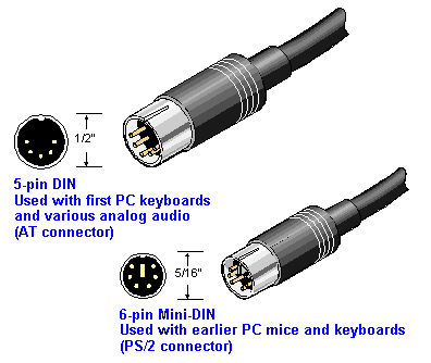
These terminals used a poorly documented variety of interface connectors, notably including RJ-45 jacks and a 5-pin DIN that resembles an AT connector but speaks a different protocol.
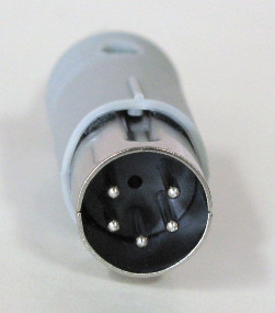
Compare this image with the AT connector shown in the next section. Note the square arrangement of the uppermost 4 pins.
Search for "RJ45 to USB Soarer’s Converter" on eBay for one possible solution. There’s a different variant of the Soarer’s Converter you might find for the 5-pin DIN; the magic search term is "240 Degree" describing the pin placement.
At time of writing in 2021, there’s a particular eBay seller named "orihalcon" who has a reputation in the keyboard-enthusiast community for making and shipping well-built Soarer’s converters. Note that there are at least three different variants of Soarer’s Converter and make sure you get the right one.
Otherwise you are deep in the weeds trying to get one of these working. One way is to get your hands on a pre-4th-generation controller PCB that speaks PS/2 or AT and transplant it in - I’ve seen this being done and it appears all versions of that PCB were very sensibly designed to mount to the case in the same way.
However: 122-key variants have a different matrix than 101-key variants and export ribbon cables with a different connector count, 20 vs. 16. Make sure your donor controller matches your ribbon cable.
Another option would be the Teensy. Model H, or Rump mods described later in this document. All 101-key Model Ms before the 4th-generation redesign used the same two (or three if there are lock lights) ribbon connectors from the sensor membrane and can thus use the same mods.
Beam-spring terminals can only be made to work with modern computers via controller replacement. Model F labs sells xwhatsit controller PCBs for two different types of beam-spring keyboard that turns them into USB devices.
XT Model M issues
Some of the very earliest variants of the Model M (1390148, 1390639, 1389969, 1390120) spoke XT protocol. Not much is known about these and it is possible they never shipped in the US.
AT Model M issues
Many older model Ms have an AT keyboard connector, using a 5-pin DIN plug larger than the PS/2 mini-DIN.
To make these work, you’ll need an AT-to-PS/2 adapter. These are no longer common, the AT connector having been phased out after the introduction of the PS/2 in 1987, but can still be found with a web search in 2021.
Then follow the next set of directions for hooking up a PS/2 Model M.
Alternatively, if your Model M has a detachable cable (later versions went to an integral cable to cut manufacturing costs), the Ethernet-like connector on the keyboard is a style called "SDL". It is sometime possible to find SDL-to-USB cables (with active converter logic) on eBay and elsewhere. Search for "USB to SDL Model M" or "SDL Soarer’s Converter"
PS/2 Model M issues
You may be able to plug your PS/2 Model M directly into a PS/2 port, if your machine still has one. But maybe not - a IBM or Lexmark Model M draws more power (100-120mA) than some modern PS/2 ports are designed to supply. Nominally PS/2 pin 4 is supposed to ship +5 V DC at 275 mA but a lot of later PS/2 implementations took advantage of the low amperage requirements of more modern keyboards (3-50mA) amd cheaped out on power management.
The high power draw remained true of older PS/2 Unicomp keyboards made to the Model M design, which had the same core keyboard electronics as late Lexmarks. The main chips on these, the Motorola 6805 processor and Intel 8042 PIC, are old and power-hungry designs.
You have two routes to recover. One (if your Model M has a detachable cable) is the aforementioned active SDL-to-USB cable. Otherwise you’ll need a PS/2-to-USB adaptor. However, not all of these will work. Passive USB adaptors, which just pass through the PS/2 signals, will fail.
Alas, the fabled "Blue Cube" active PS/2 to USB adapter seems to have been discontinued. However, the Sanoxy adapter has been reported to work.
PS/2 Unicomp issues
At https://deskthority.net/viewtopic.php?f=2&t=25718 there’s a resort that PS/2 Unicomps do not report Ctrl-Pause correctly as a Break scancode. Unicomp is aware of the issue.
USB Unicomp issues
Unicomp keyboards prior to the 2020 "New Model M" could be purchased with a USB interface, but had continuing interoperability problems.
Boot-mode problems
The UB HID standard describes two ways that keyboards can behave on power-up. There is a normal "report mode" and "boot mode" which interrupts the CPU every time the keyboard is polled; this is intended to allow the BIOS to handle a USB keyboard in the absence of a USB-aware operating system. USB keyboards are supposed to come up in report mode, and be switched into and out of boot mode by your host system’s BIOS.
Some (but not all) older Unicomp model Ms may not have correctly responded to the control sequence telling them to drop into boot mode mode. Suspect this if yours won’t talk to a PC at boot time and has to be unplugged/replugged to establish communication with the PCS’s internal hub. Alas, there is no fix; the workaround is the unplug/replug.
We have one report that even the prototype SSK version of the New Model M (part number UB40E7A) needs to be unplugged and replugged after boot. Possibly this was fixed in production versions; I have seen no such issue with my full-sized production New Model M (UT40U4A).
(The CY8C24493 the prototype SSK is using as a controller draws 250mA, which is pretty high for a keyboard without RGB lights, but runs on anything between 1.7v and 5.5v so this is definitely not an undervoltage issue.)
A subtler problem arises because some PC hubs fail to transmit the command required to switch a USB keyboard in boot mode to normal mode after boot. If this does not occur, the keyboard will be limited to 6-key rollover rather than supporting the N-key rollover of normal-mode USB. This limit is never pushed by older model Ms, which due to the way their sensor matrix is constructed are limited to 2KRO, but may be an issue with the Unicomp Mini-M SSK which has a reworked larger matrix with individual traces for the WASD cluster.
Controller incompatibility
I have checked operation of two Unicomp keyboards on each of two test machines. One, snark, uses an Intel NM10/ICH7 (rev 01) USB controller. The other, minx, uses an AMD SB7x0/SB8x0/SB9x0 USB controller.
-
A UB40PGA (the nipple mouse variant, "EnduraPro") manufactured in Oct 2012 works reliably on both machines.
-
A UB404LA (the trackball variant, "Ruffian") manufactured in Oct 2012 has flaky behavior on both machines. On minx it disconnects from the hub every few minutes, needing to be replugged. On snark it has once failed to register at boot time but is generally reliable.
We have a confirming report from one Alex Lustenberg, in a comment here, that the UB404LA is flaky even as the only device on his machine and doesn’t enumerate on boot.
Alex also reports the UB404LA failing to initialize correctly with these host controllers: NVIDIA MCP55 (rev a1/a2), Intel series/C200 series (rev 05), and NEC uPD720200 (USB3).
Undervoltage sensitivity
Alex Lustenberg reports "according to some accounts, the USB controller in the unicomp isnt exactly USB compatible; undervoltage within USB spec will cause it to not init properly"
This post and its comments display some evidence that undervoltage probably isn’t an issue, but a keyboard controller failure to respond properly during the initialization sequence may be.
This theory is reinforced by experiments with two cheap hubs containing the Terminus Manufacturing 4-port USB hub chip (1a40:0101) and a hub containing a chip by Genesys Logic, Inc. (05e3:0608). The UB404LA fails to initialize on powerup connected to either of these, but becomes visible when unplugged and replugged. The UB40PGA exhibits normal behavior.
I disassembled the UB404LA and found that the only chip in it is a Cypress 24794 SOC (manufacturer data sheet here) sitting on a mini PCB behind the LED panel that is wired to both the USB cable and the keyboard proper.
I also disassembled the UB404PGA. There are two chips on the mini-PCB in this one, an LM393 differential comparator and a CY763513-PVC (data sheet here).
The key point about these Cypress chips is that while they’re both USB controllers they’re different SOCs; it could easily be that the USB stage in the first is flawed but the second is not.
We have a report that flaky failures on a UB40B5A (the 122-key variant) were resolved by plugging it into the sort of high-amperage USB2 port used to recharge cellphones.
On the other hand, the undervoltage theory gets a boost from one Andrew Hutchings, who reports: "I’ve just come back from a micro electronics lab where we have been testing [the Cypress 24794 SOC on a Ruffian v2 board] and it seems the problem is to do with voltage. If the USB port is 4.9-5.0v it works fine, 5.1-5.2v the handshake does not succeed." A day later he said "We jury-rigged a TPS73150 regulator in front of the USB power input to the PCB. It now works perfectly on every PC and powered hub I have. Not sure how permanent a fix it is but it will do until I can buy a replacement PCB from Unicomp."
I can no longer recommend buying any of these older Unicomp models. The New Model M appears to have solved the USB incompatibility issues of older Unicomps. In addition, it is plainly visible from the finish of the case and keycaps that they bought new tooling to produce these and the build quality has gone way up.
Cable failure due to nonexistent strain relief
It has been reported in a comment attached to sa now vanished G+ post that one UB4044A (Classic Black with no pointing device) has exhibited intermittent USB disconnect issues which turned out to be cable failure; there is no strain relief where the USB cable enters the keyboard.
I have opened up the UB404LA and UB404PGA, both manufactured in October 2012, and verified that there is no strain relief on the USB cable. It looks like this is a consistent design error across the Unicomp USB line - up to and including the full-size New Model M - that may account for a lot of problems. It’s inherited from the fixed-cable Lexmark and IBM versions, which didn’t have strain relief either.
One product that does not have this issue is the narrow tenkeyless (SSK) version of the New Model M. It has a USB A connector in the rare locking variant on the keyboard chassis, and a cable that mates with it And has a conventional Model A connector on the other end.
Power usage
The UB404PGA reports 98mA draw and says it is "Bus Powered"; the UB404LA reports 100mA draw and says it is "Self Powered". The USB 2.0 spec allows a 500mA draw.
On opening up these keyboards, I discovered that both use Cypress programmable SOCs, replacing the 6805/8042 found on older Model Ms. These are low-power chips that should have no issues drawing from a USB 2.0 controller.
On this evidence, I think the theory that the Unicomps still have the Model M’s physical power-draw issues can be dismissed. However, there is evidence that some sort of logic error triggered by under-voltage or under-amperage may have mimicked such problems in several Unicomp models pror to the New Model M; refer to the previous section on USB Unicomp issues for details.
Buggy firmware on Unicomp Mini-M
The firmware on the Unicomp Mini-M is flaky. The most common bugs is the Q key becoming unresponsive; also it sometimes fails to work when the host system is reawakened from a sleep state. Usually these problems can generally be fixed by unplugging and replugging the keyboard.
The full-sized New Model M doesn’t have this problem.
Reaching Unicomp technical support
I haven’t found a way to reach a live human being yet. The Unicomp website carefully avoids giving any technical support email addresses or phone numbers. The company has a main number at (859) 233-2130, but you can’t get to an engineer that way.
You can open support tickets through support@pckeyboard.com and I have received replies.
Model F issues
Keyboards speaking XT protocol are not directly usable with modern machines, even with the dual-adaptor setup described for the Model M. IBM changed the Model M’s keyboard scan codes in a way seriously incompatible with the Model F.
(This change wasn’t done gratuitously; the microcontroller technology of the time made it expensive to assign scan codes in violation of a natural sequence determined by the wire layout. And no, I don’t know how that squares with the reports of very early Ms speaking XT protocol.)
One variant of the "Soarer’s Converter" family of active cables bridges the gap from the F to USB.
Mods and hacking
Bumper modding
Despite the weight of the Model M, some case variants have a tendency to skid around on a smooth desk surface, expecially on a glass-topped desk. Serious typists can forestall this by applying stick-on rubber or cork bumpers to the case bottom.
On an M, there are two 5mm x 5mm square-shaped contact areas adjacent to the wells that the fold-out feet sit in, and/or near the front corners of the case. Lots of places on line sell neoprene stick-on-feet in that size: search for "5mm square rubber feet".
Model Fs ship with 4 cork feet that are disks 1" in diameter and 1/16" thick. They have a tendency to disintagrate or peel off over time. Model F Labs can sell you exact matches for the originals, and the same can sometimes be found on eBay at "Model F pads"; if you’re less fussy about color, there are many sources on line.
(Note: If you find an exact match from an original vendor, please email me so I can cite it here.)
Bolt modding
The Model M is a notoriously rugged device which routinely clocks in a service life of over 30 years. However, it has one known mechanical failure mode. Its metal backplate is secured to the barrel plate holding the keyswitches by a large number of plastic rivets protruding through holes in the backplate.
Over decades these can degrade and break, affecting key feel and in extreme cases rendering the device inoperable. You can tell this is required if you hear rivet fragments rattling around when you shake the keyboard.
Function can be restored with a procedure called a bolt mod that replaces the rivets with bolts or screws.
There are two different ways to bolt-mod. You can do it in-place ot full-disassembly. Either will require the following tools and supplies:
-
5.5mm nut driver
-
Hobby blade
-
Dremel tool or cordless drill with 1/16 bit
-
4mm nut diver
-
#1 Phillips head screwdriver
-
M2 screws, 10mm, McMaster Carr 92005A033
-
M2 nuts, McMaster Carr 90592A004
-
M2 washers, McMaster Carr 93475A196
There are helpful videos of the full-disassembly procedure on YouTube; the best I’ve found is this one. To do his procedure as described you will need one additional tool: a pair of nail nippers.
You may prefer to trim off the rivet stubs with flush-cut nippers - I found this worked better than nail nippers. Those are cheap anywhere that sells electrician’s tools. Harbor Freight sells very inexpensive "Micro Flush Cutters" that are an ideal size for this job.
Flexing the barrel plate to pry it loose risks cracking it. Instead, push out each of the the rivet stems with a screwdiver tip.
Note that keyfiender uses 8mm screws with a different McMaster Carr part number; I’ve found these don’t leave enough room for both washer and nut on some older Model Ms with thicker plates.
Rather than using 10mm screws, you can stick with keyfiender’s 8mm screws (McMaster Carr part number 92005A029) but omit the washers. If you omit the washers it’s a good idea to seal the nuts with Loctite - use Loctite Purple so turning the nut with a hand tool can break the adhesion when required without risking stripping the screws. Best to do this only when the keyboard is verified working.
There is also the screw mod, described some way down in Bitten’s Model M Restoration Megaguide. I haven’t tried his self-tapping screws. I have used self-forming screws, driving in the screws from the backplate side. This method doesn’t require the nuts, but you will need the washers under the screw heads on the plate side.
I shall at some point try this with M2 screws with a 3.5mm head width, which should eliminate the need for washers entirely.
Keyfiender says that the row of rivers right near the low board edge (where the spacebar is) don’t need screws, but diesn’t explain why. Answer: if you have the rest of the plate assembly properly riveted, that edge of the barrel plate won’t flex enough to natter. Also putting nuts on the barrel plate there interferes with how it sts in the pan.
I recommend wearing a filter mask while drilling as the process generates fine particulates that are not friendly to your lungs. Also, getting 8 or so cheap 3-inch spring clamps and clamping them on the edges of the plate assembly will ensure that when it’s inverted on your work surface the springs protruding from the barrel plate don’t drag and get damaged.
A subtle gotcha in full reassembly: It is normal for there to be one unfilled barrel on an M101, which you might have missed if you weren’t paying attention. This is what the flappers should look like when reassembling:

Note where the unfilled barrel is at the lower right, between LAlt and the spacebar.
In-place is the easier way. Use it if you’re confident the sensor membranes are clean and undamaged. Simply invert your M and, without dissassmbling it, drill out the holes from the backplate side. Apply bolts and nuts as you drill so the plate assembly never separates.
The one risk of the in-place mod is that if you don’t make clean holes at an appropriate low-speed setting (15000rpm works well) you may push fragments of plastic between the sensor membranes that interferes with operation. Test thoroughly; if you have unresponsive kewys your fallback is to take out all the bolts, disassemble the plates, and clean everything up before proceeding.
There turn out to be 48 bolt positions on my 1988 1391401.
Having done both in-place bolt mods and keyfiender’s full-disassembly technique, I can report that you really want to de-burr the entry hole for each screw, otherwise you’ll have a miserable time trying to get them started. I inserted the point of a triangular hobby blade so both edge and back contracted the edges of the hole, then twisted it around applying light pressure.
Also, go easy on tightening the nuts and bolts. The screws are not particularly hard steel and their threads are very fine; it’s easy to strip them by overtightening. Even when you don’t strip the bolts, if you tighten the down too much you can compress the plate essembly enough to force some sensor locations permantly closed, deadening sections of the keyboard or even the entire thing. If your keyboard is unresponsive after a bolt mod, loosen it up.
I recommend the Picquic "Teeny Turner" for screwing in the bolts. The effect of the magnetic tip makes it easier to place the screws in tight locations
Dremel, Inc. sells a thing it calls a "WorkStation" that’s like a baby drill-press mount for its Dremel tools. If you are as unsure of your ability to drill true vertical holes as I am, you’ll find it very useful.
Floss Modding
The Model M (and even more the Model F) is quite noisy compared to modern keyboards, and this is not to everybody’s taste. There’s a procedure called a "floss mod" that consists of inserting little lengths of dental floss or paracord core fibers down the middle of each buckling spring. This considerably reduces the action noise, especially the pingy high-freqency transients.
Be careful to trim the fibers flush with the spring tops rather than allowing them to protrude, as protruding ends can degrade the crispness of the key feel.
Retrojacking
This is a term I coined for a mod that exploits the way Lexmark did their fixed-cable cheapout to make an SDL jack magically appear in your case.
This mod becomes necessary because the fixed cables are flimsy and their insulation has a nasty tendency to fray, especially where it attaches to the strain reliever (the gray rectangle of plastic where the cable meets the case). This can actually make the keyboard an electrical hazard.
-
Open the case of your M and take off the top half. Look at the rear edge and note the number and lead count of ribbon cables going to the PCB. Usually it’s going to be either 16-8-4 or 16-12.
-
The hard part: get your hands on an M controller board with an SDL jack and sockets matching your ribbon cables, and which is the same size or smaller than your installed board. You’ll need an SDL cable, too. These parts can sometimes be salvaged from Ms that are too beat up to be restored. Or they can sometimes be purchased on eBay.
-
Disengage your cable. Start by pulling the male Molex plug terminating it from its socket on the PCB; you may also need to unbolt a ground wire running from the cable to the backplate.
-
Free the cable. At one rear corner of the PCB there’s a small plastic shim with Mickey Mouse ears, each surrounding a vertical peg; pull it up and out. Lo! An SDL-jack aperture magically appears!
-
Extract the cable. Push the Molex plug through the jack aperture.
-
The board is held in place by the pegs you revealed in step 4, and possibly by two plastic clips to the rear. Lift it off the pegs.
-
Align the jack on your replacement board with the recently-revealed jack aperture and drop your replacement board onto the pegs (and into the clips if present). Connect up the ribbon cables.
That’s it. Your M now has a jack and a sturdier cable.
Conversion and controller mods
The easiest way to adapt a pre-USB Model M to do USB is to use an adapter that plus into the existing cable. Some people are unsatisfied with this, preferring a modification inside the Model M’s case and exposing a USB jack or cable. One reason for this dissatisfaction is power drain issues.
Several people have published USB conversion mods using the Teensy development board. You can find them by searching the Web for "model m teensy"; this one is representative. These don’t replace the keyboard controller; instead they mount the Teensy connected to it inside the case to do protocol conversion and provide a USB micro-B jack.
Mods that replace the controller are more difficult, and generally require a small custom PCB. While they are generally open-source, none has yet made it to true volume production.
The Model H by John Hawthorn comes in two different variants, one to match each of the two earlier (16-8-4 and 16-12) configurations of Model M ribbon cables. It uses the actively maintained and well documented QMK firmware.
The Rump Mod by Chris Lee replaces the Model M’s controller with a tiny custom PCB running open-source keyboard firmware.
The TMK converter is an internal mod that covers all F XT and F AT keyboards. Because the F controller is integrated on to the sensor PCB, this mod mod doesn’t replace it. Rather, a micrboard plugs into the connector exposed by the stock controller and exports its own controller cable.
Related resources
- Wikipedia on the Model M
-
History of the device and how to identify variants.
- Hardware Interface Technical Reference, Keyboard 101- and 102-Key
-
IBM’s interface manual for the M101.
- https://ardent-tool.com/docs/patent/US4118611.pdf
-
The buckling-spring patent.
- IBM Enhanced Keyboard
-
Lots of information on the history of the product.
- Care and feeding of the IBM Model M keyboard
-
Just what it says on the tin; applies to Unicomps as well. Particularly good stuff about how to clean the beast.
- Unicomp
-
The only place to buy new Model Ms.
- http://www.clickykeyboards.com/
-
Resells vintage IBM Model Ms (and occasionally Model Fs) scavenged from various sources.
- http://www.ebay.com/sch/sis.html?_kw=IBM+Model+M+Buckling+Spring+keyboard
-
Various vendors on eBay sell used and reconditioned Model Ms. Quality is much more hit or miss than if you buy from www.clickykeyboards.com, beware.
- Model F Labs
-
Produces an authentic though expensive clone of the Model F.
- https://www.ebay.com/str/barcodemaverick/Vintage-Keyboards-Cables/_i.html?_storecat=7992169018
-
orihalcon’s eBay store.
- Tactile Keyboard FAQ
-
Many links to related resources can be found at this FAQ.
- https://www.youtube.com/watch?v=r5H58uudo1Y
-
Thomas Ran’s "The Ultimate IBM Model M review"
- https://swvincent.com/ibm-model-m-power/index.html
-
Power consumption of IBM Model M Keyboards
- https://www.reddit.com/r/MechanicalKeyboards/wiki/modifications_ibm#wiki_model_m_repair
-
Links to many articles on repairing and modifying the Model M.
- http://boxes.shippingsupply.com/Shop/P20104-C60.aspx
-
Best fit I’ve found in shipping boxes for a Model M, 20"x10"x4".
- https://github.com/tmk/tmk_keyboard/wiki/IBM-PC-XT-Keyboard-Protocol
-
Very detailed reverse engineerung if IBM XT protocol.
History
This document is a tale that grew in the telling. It started out as a series of bug notes about problems with the USB controllers on Unicomp model Ms, and expanded as the author learned more about troubleshooting and restoring buckling-spring keyboards.
- 2.2: 2001-08-31
-
TMK controller, and a video on spacebar installation.
- 2.3: 2001-09-12
-
Web keyboard testsers, uses of Q-tips, what a stuck key looks like.
- 2.1: 2001-08-16
-
Conductive-ink pens don’t work. Use 10mm screws and a mask for bolt modding. The use of LocTite.
- 2.1: 2001-08-12
-
Describe the M spring-replacement procedure. In-place bolt modding.
- 2.0: 2001-08-10
-
Name change to "The Compleat Classic Keyboard."
- 1.34: 2001-08-09
-
Details on how to reassemble a Model F.
- 1.33: 2001-08-06
-
More restoration advice.
- 1.32: 2001-07-23
-
Restoration philosophy. The collectibility gradient. About keycaps.
- 1.31: 2001-07-20
-
Describe the retrojacking mod.
- 1.30:2001-07-15
-
Avoiding F spacebar breakage. The right size of Pozidriv.
- 1.29:2001-07-10
-
Much more on diagnostics. More on F disassembly. Dimensions of bumpers.
- 1.28: 2001-07-08
-
A better bolt-mod video. Describe the Model H. Three board generations.
- 1.27: 2021-07-02
-
More on Model F restration.
- 1.26: 2021-06-29
-
Links to Model F mat templates.
- 1.25: 2021-06-27
-
Ctrl-Pause issue with Unicomp PS/2 keyboard. Dealing with rust and mold.
- 1.24: 2021-05-19
-
Coverage of beam-spring keyboards.
- 1.23: 2021-05-18
-
Note incompatibility among product generations. The perils of dishwashers. Terminal Ms.
- 1.22: 2021-05-15
-
Mention the Teensy mods.
- 1.21: 2021-05-10
-
The Blue Cube is dead. Long live the Sanoxy adapter.
- 1.20: 2021-05-09
-
Explain boot-mode issues.
- 1.19: 2021-05-08
-
Added Thomas Ran’s table.
- 1.18: 2021-05-05
-
Note existence of Model Ms speaking XT protocol. Describe bolt, floss, and spacer modding. How to clean and test.
- 1.17: 2021-04-28
-
The full-sized New Model M has no strain relief, alas.
- 1.16: 2021-04-26
-
Note the existence of Soarer’s Converter for the old Model F. Mention the new Model F. Add some links.
- 1.15: 2021-04-24
-
Controller incompatibility on the Unicomp SSK, correct "Phillips" to "Pozidriv", add history section.
- 1.14: 2021-04-18
-
Update for the Unicomp New Model M.